Building a USB SNES Controller
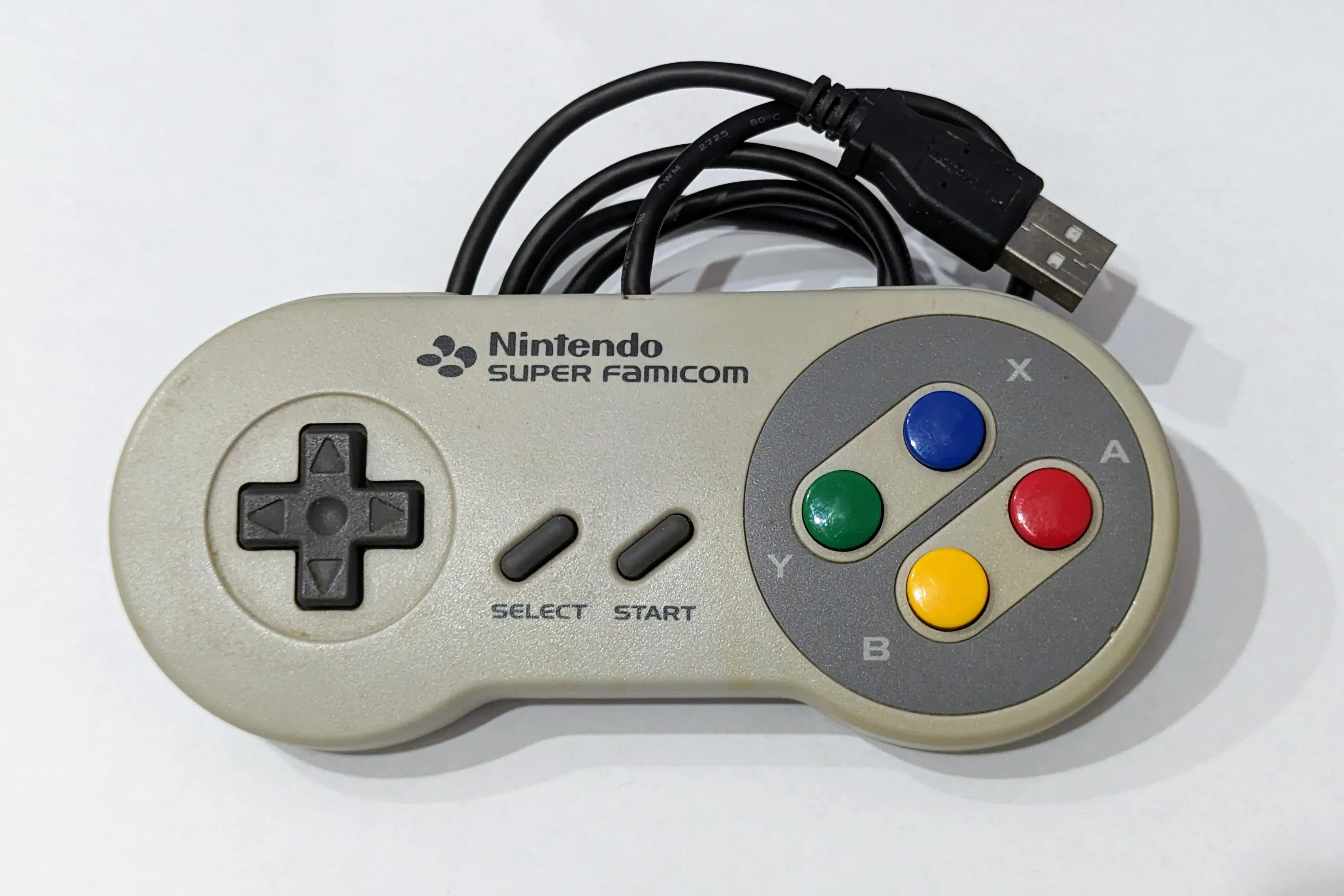
A few years ago on a trip to Tokyo, we took a day to explore Akihabara. We found a shop that was selling retro gaming stuff and when I saw an old SNES controller for sale I had to buy it.
Playing the SNES was one of my favourite things as a kid and Secret of Mana remains one of my favourite games to this day.
Of course, I didn’t have a SNES console anymore so when we returned back home I decided it would be a fun project to modernize the SNES controller so I could plug it straight into my PC via USB.
SNES Controller Hardware
The first step was to figure out how the SNES controller hardware reported which buttons were being pressed. After a bit of Googling I found this document describing the hardware.
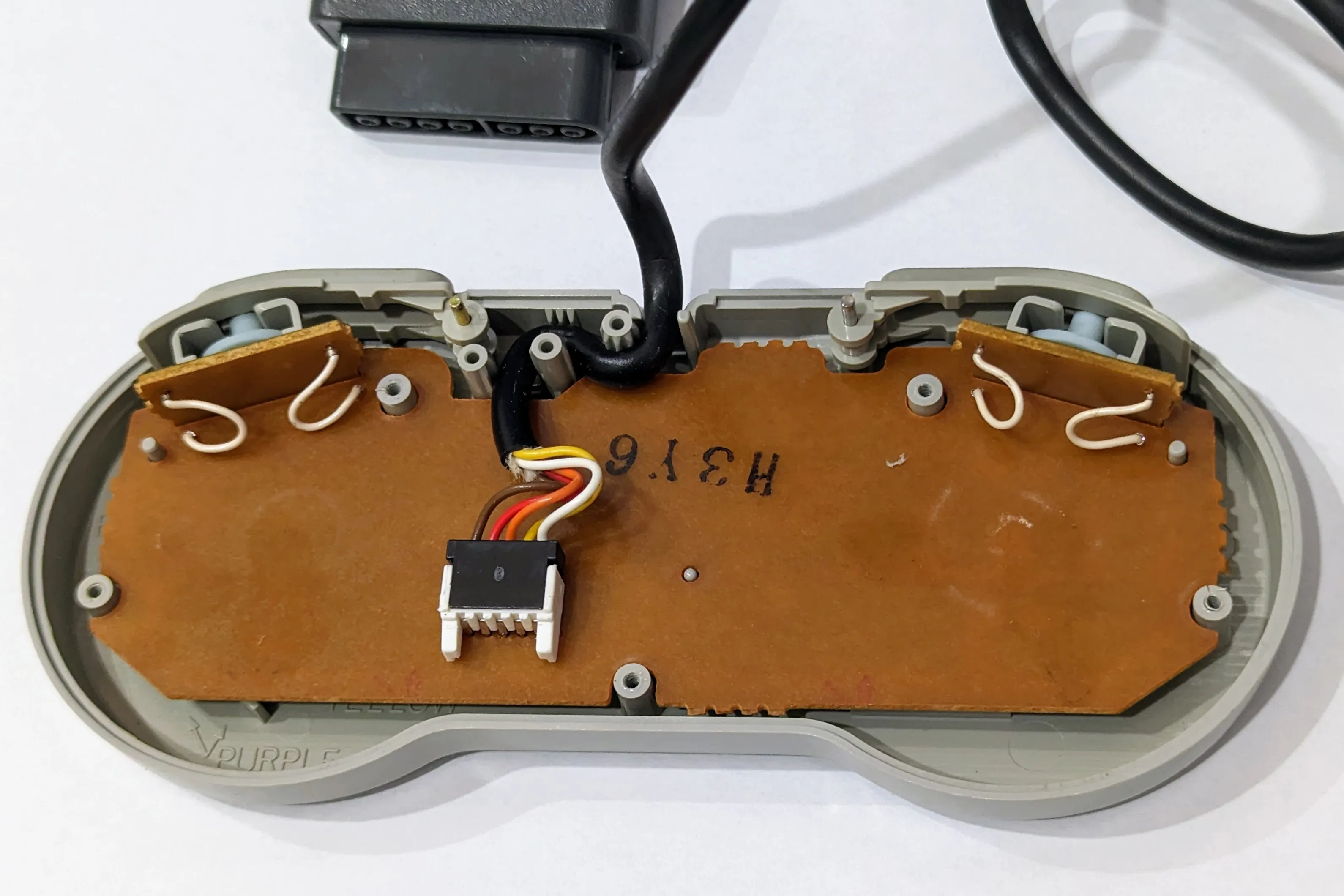
Luckily I now have another unmodified SNES controller so I can take some pictures of the original hardware.
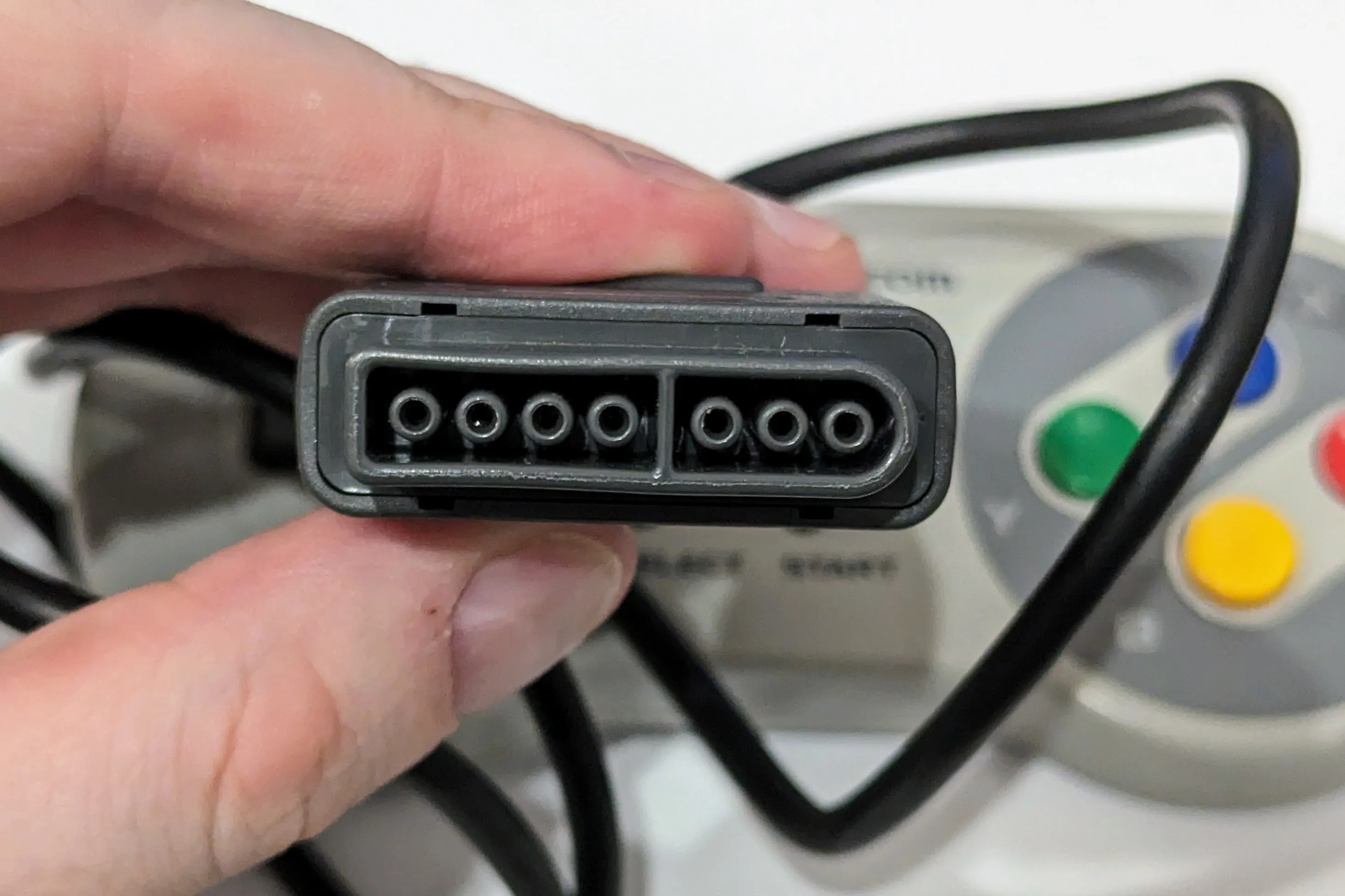
The pins of the plug from left to right are:
| Pin | Purpose | Internal Wire Colour |
|---|---|---|
| 1 | +5v power line | White |
| 2 | Data clock | Yellow |
| 3 | Data latch | Orange |
| 4 | Serial data | Red |
| 5, 6 | Nothing | No wire |
| 7 | Ground | Brown |
Pins 2 and 3 are driven by the console and begin high and low respectively. Pin 4 is driven by the controller.
The document above also described the process the SNES console used to read which buttons of the controller were pressed. The gist is:
- Send a 12us high pulse on pin 3.
- Wait 6us.
- If pin 4 is low, the B button is pressed.
- Send a 6us low pulse followed by a 6us high pulse on pin 2.
- Repeat the previous 2 steps for all of the remaining buttons in order (Y, Select, Start, Up, Down, Left, Right, A, X, L, R) and then 4 extra times with no corresponding button.
- Repeat the whole process every 16.667ms (60Hz)
Programming the Arduino
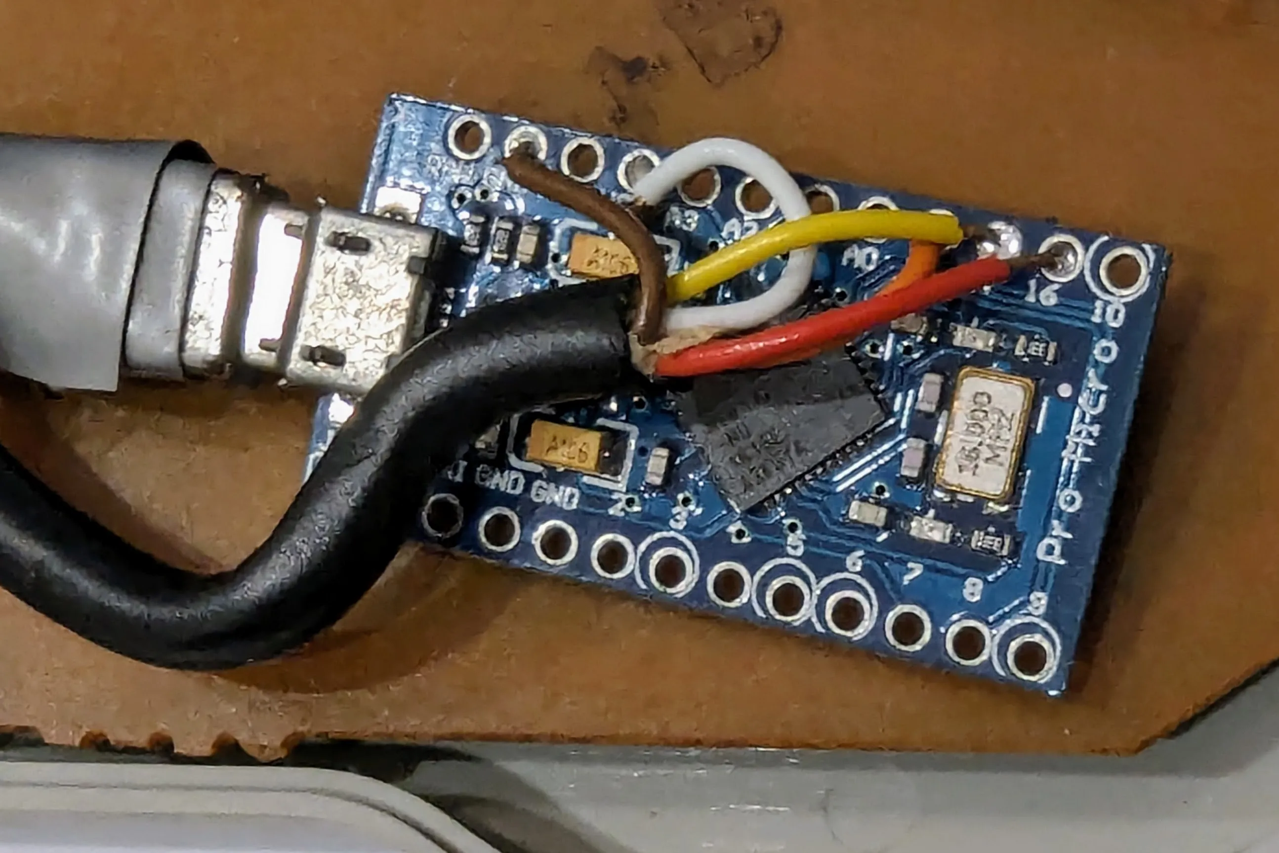
Next I needed something that could perform the above steps and relay the result to the connected computer. I decided on a tiny board based on the ATmega32u4 chip as it was small enough to fit inside the controller and could power the controller at the right voltage.
I connected the wires inside the SNES controller to the pins of the board:
| SNES Controller Wire | Arduino Pin |
|---|---|
| White | VCC |
| Brown | GND |
| Yellow | 14 |
| Orange | 15 |
| Red | 16 |
Coding up the button scanning process on the Arduino looks like this:
#define CLOCK_PIN 14#define LATCH_PIN 15#define DATA_PIN 16
const uint8_t num_buttons = 16;
void setup() {  pinMode(CLOCK_PIN, OUTPUT);  pinMode(LATCH_PIN, OUTPUT);  pinMode(DATA_PIN, INPUT);
  digitalWrite(CLOCK_PIN, HIGH);}
void loop() {  // Collect button state info from controller.  // Send data latch.  digitalWrite(LATCH_PIN, HIGH);  delayMicroseconds(12);  digitalWrite(LATCH_PIN, LOW);
  delayMicroseconds(6);
  bool button_states[num_buttons];
  for (uint8_t id = 0; id < num_buttons; id++) {    // Sample the button state.    int button_pressed = digitalRead(DATA_PIN) == LOW;    button_states[id] = button_pressed;
    digitalWrite(CLOCK_PIN, LOW);    delayMicroseconds(6);    digitalWrite(CLOCK_PIN, HIGH);    delayMicroseconds(6);  }
  delay(16);}
(Note: Since the poll takes around 210us, delaying for 16ms after each poll means my controller polls slightly faster than 60Hz but I figured it was close enough.)
Connecting to a Computer
So now the Arduino knows which buttons are pressed (in button_states) so how does it get that information to the connected computer?
Peripherals like keyboards, mice and gamepads talk to the computer they are connected to through the HID protocol. I used the Arduino HID Project library to program the Arduino as a HID gamepad.
Near the top of the code I imported the library, defined a constant for the index of every SNES button in the button_states array and created a mapping from each SNES button to the HID gamepad button I wanted it to correspond to:
#include <HID-Project.h>
#define SNES_BUTTON_B 0#define SNES_BUTTON_Y 1#define SNES_BUTTON_SELECT 2#define SNES_BUTTON_START 3#define SNES_BUTTON_UP 4#define SNES_BUTTON_DOWN 5#define SNES_BUTTON_LEFT 6#define SNES_BUTTON_RIGHT 7#define SNES_BUTTON_A 8#define SNES_BUTTON_X 9#define SNES_BUTTON_L 10#define SNES_BUTTON_R 11#define SNES_BUTTON_UNDEF_1 12#define SNES_BUTTON_UNDEF_2 13#define SNES_BUTTON_UNDEF_3 14#define SNES_BUTTON_UNDEF_4 15
// Map SNES buttons to HID joypad buttons.const uint8_t snes_id_to_hid_id[] = { 2, 4, 7, 8, 0, 0, 0, 0, 1, 3, 5, 6, 10, 11, 12, 13 };
I’m not sure why I chose this mapping or if it matters how the buttons map beween the SNES and the HID gamepad buttons, but I’m sure I had a good reason for this mapping at the time.
In the setup function I needed to initialize the library:
Gamepad.begin();After every button scan cycle I updated the library’s state based on the values in the button_states array (with some special logic for the D-pad) then reported those values to the computer with Gamepad.write():
// Report button states over HID.void reportButtons(bool button_states[num_buttons]) {  // D-Pad.  int8_t dpad_status = GAMEPAD_DPAD_CENTERED;
  if (button_states[SNES_BUTTON_UP]) {    dpad_status = GAMEPAD_DPAD_UP;    if (button_states[SNES_BUTTON_LEFT]) {      dpad_status = GAMEPAD_DPAD_UP_LEFT;    } else if (button_states[SNES_BUTTON_RIGHT]) {      dpad_status = GAMEPAD_DPAD_UP_RIGHT;    }  } else if (button_states[SNES_BUTTON_DOWN]) {    dpad_status = GAMEPAD_DPAD_DOWN;    if (button_states[SNES_BUTTON_LEFT]) {      dpad_status = GAMEPAD_DPAD_DOWN_LEFT;    } else if (button_states[SNES_BUTTON_RIGHT]) {      dpad_status = GAMEPAD_DPAD_DOWN_RIGHT;    }  } else if (button_states[SNES_BUTTON_LEFT]) {    dpad_status = GAMEPAD_DPAD_LEFT;  } else if (button_states[SNES_BUTTON_RIGHT]) {    dpad_status = GAMEPAD_DPAD_RIGHT;  }
  Gamepad.dPad1(dpad_status);  Gamepad.dPad2(dpad_status);
  for (uint8_t snes_id = 0; snes_id < num_buttons; snes_id++) {    if (snes_id >= 4 && snes_id <= 7) {      // D-Pad.      continue;    }
    if (button_states[snes_id]) {      Gamepad.press(snes_id_to_hid_id[snes_id]);    } else {      Gamepad.release(snes_id_to_hid_id[snes_id]);    }  }}
void loop() {  ...
  // Update HID button states.  reportButtons(button_states);  Gamepad.write();
  delay(16);}
Putting it all Together
After making sure the computer was recognising the Arduino as a HID gamepad and seeing all the button presses, I soldered the wires onto the Arduino pins.
At this point I tried putting the Arduino into the controller and closing it back up but there wasn’t enough room for the board and the cable so I had to remove parts of the supports on the back cover.
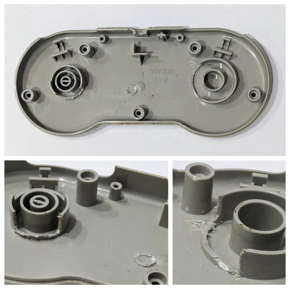
Now the Arduino just about fit inside.

To celebrate, I played a race of Super Mario Kart with that authentic controller experience! 🏎️🏎️🏎️🏁
Appendix
The complete Arduino code:
#include <HID-Project.h>
#define CLOCK_PIN 14#define LATCH_PIN 15#define DATA_PIN 16
#define SNES_BUTTON_B 0#define SNES_BUTTON_Y 1#define SNES_BUTTON_SELECT 2#define SNES_BUTTON_START 3#define SNES_BUTTON_UP 4#define SNES_BUTTON_DOWN 5#define SNES_BUTTON_LEFT 6#define SNES_BUTTON_RIGHT 7#define SNES_BUTTON_A 8#define SNES_BUTTON_X 9#define SNES_BUTTON_L 10#define SNES_BUTTON_R 11#define SNES_BUTTON_UNDEF_1 12#define SNES_BUTTON_UNDEF_2 13#define SNES_BUTTON_UNDEF_3 14#define SNES_BUTTON_UNDEF_4 15
const uint8_t num_buttons = 16;
// Map SNES buttons to HID joypad buttons.const uint8_t snes_id_to_hid_id[] = { 2, 4, 7, 8, 0, 0, 0, 0, 1, 3, 5, 6, 10, 11, 12, 13 };
void setup() {  Gamepad.begin();
  pinMode(CLOCK_PIN, OUTPUT);  pinMode(LATCH_PIN, OUTPUT);  pinMode(DATA_PIN, INPUT);
  digitalWrite(CLOCK_PIN, HIGH);}
// Report button states over HID.void reportButtons(bool button_states[num_buttons]) {  // D-Pad.  int8_t dpad_status = GAMEPAD_DPAD_CENTERED;
  if (button_states[SNES_BUTTON_UP]) {    dpad_status = GAMEPAD_DPAD_UP;    if (button_states[SNES_BUTTON_LEFT]) {      dpad_status = GAMEPAD_DPAD_UP_LEFT;    } else if (button_states[SNES_BUTTON_RIGHT]) {      dpad_status = GAMEPAD_DPAD_UP_RIGHT;    }  } else if (button_states[SNES_BUTTON_DOWN]) {    dpad_status = GAMEPAD_DPAD_DOWN;    if (button_states[SNES_BUTTON_LEFT]) {      dpad_status = GAMEPAD_DPAD_DOWN_LEFT;    } else if (button_states[SNES_BUTTON_RIGHT]) {      dpad_status = GAMEPAD_DPAD_DOWN_RIGHT;    }  } else if (button_states[SNES_BUTTON_LEFT]) {    dpad_status = GAMEPAD_DPAD_LEFT;  } else if (button_states[SNES_BUTTON_RIGHT]) {    dpad_status = GAMEPAD_DPAD_RIGHT;  }
  Gamepad.dPad1(dpad_status);  Gamepad.dPad2(dpad_status);
  for (uint8_t snes_id = 0; snes_id < num_buttons; snes_id++) {    if (snes_id >= 4 && snes_id <= 7) {      // D-Pad.      continue;    }
    if (button_states[snes_id]) {      Gamepad.press(snes_id_to_hid_id[snes_id]);    } else {      Gamepad.release(snes_id_to_hid_id[snes_id]);    }  }}
void loop() {  // Collect button state info from controller.  // Send data latch.  digitalWrite(LATCH_PIN, HIGH);  delayMicroseconds(12);  digitalWrite(LATCH_PIN, LOW);
  delayMicroseconds(6);
  bool button_states[num_buttons];
  for (uint8_t id = 0; id < num_buttons; id++) {    // Sample the button state.    int button_pressed = digitalRead(DATA_PIN) == LOW;    button_states[id] = button_pressed;
    digitalWrite(CLOCK_PIN, LOW);    delayMicroseconds(6);    digitalWrite(CLOCK_PIN, HIGH);    delayMicroseconds(6);  }
  // Update HID button states.  reportButtons(button_states);  Gamepad.write();
  delay(16);}